Surface Finish: Specify What Matters, Save What Doesn't
Surface finish (often called surface roughness) defines how smooth a surface must be after manufacturing. Tighter finishes increase cycle time, tool wear, scrap risk, and inspection effort—so only specify them where function demands.
Ignoring surface finish leads to quoting misses and rework. Use this guide to call out finishes that protect function without inflating cost.
At‑a‑glance
- Cost driver: Finer Ra/Rz → slower feeds/speeds and extra steps (e.g., grinding, honing, lapping).
- Be selective: Apply tight finishes only to mating, sealing, wear, or optical/cosmetic surfaces.
- Default smartly: Use a general note for non‑critical faces (e.g., “Unspecified surfaces ≤ 6.3 µm Ra (N9), break sharp edges”).
- State the parameter & units: Always say Ra or Rz and µm or µin. Avoid bare numbers.
Unit quick‑convert: 1 µm ≈ 39.37 µin. Keep a single unit family across a drawing whenever possible.
Standard symbols (ISO style)
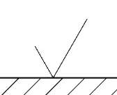
Basic surface texture symbol
The basic symbol indicates a surface requirement without implying how it is made.
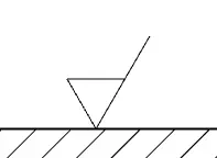
Material removal required
A short bar added to the basic symbol means material must be removed by a machining process. Provide stock allowance if needed.
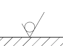
Material removal prohibited
A small circle added to the basic symbol means the surface must be obtained without later machining (e.g., as‑cast, as‑forged, die‑cast, injection‑moulded).
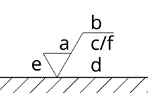
What the callout means (parameters on/near the symbol)
The labeled elements below are commonly used on surface texture callouts. Not every callout uses all fields.
- a — primary roughness value (e.g., Ra 3.2 µm)
- b — production method, coating, or free text (e.g., grind, anodize after milling)
- c — roughness sampling length (cut‑off) in mm or in (e.g., 2.5 mm)
- d — lay direction (texture orientation)
- e — minimum material removal (stock allowance) in mm
- f — alternate/secondary parameter (e.g., Rz 16 µm)
Lay direction codes (common)
- — parallel to the reference
- ⊥ perpendicular
- X crossed
- M multidirectional
- C circumferential (around an axis)
- R radial (from a center)
- N non‑directional
If lay matters (for sealing or sliding), state it. Otherwise suppliers must guess, which invites misses.
Typical ranges by process (rule‑of‑thumb)
| Process / condition | Typical Ra (µm) | Approx. N‑grade | Notes |
|---|---|---|---|
| As‑cast / as‑forged | 12.5 – 50 | N9 – N12 | Specify “material removal prohibited” if final surface must remain as‑made |
| General milling/turning | 1.6 – 6.3 | N7 – N9 | Most economical zone for non‑critical faces |
| Fine turning / reaming | 0.8 – 1.6 | N6 – N7 | Often achievable without secondary ops |
| Grinding | 0.2 – 0.8 | N4 – N6 | Adds an extra setup and inspection step |
| Honing / lapping / superfinishing | 0.05 – 0.2 | N2 – N4 | For sealing, bearing, optics; highest cost impact |
Values are indicative. Capability varies by material, tool, machine, and part geometry.
N‑Grades (normalized scale)
Surface parameters can be specified in different ways (Ra, Rz, Rt, Rq) and units. N‑Grades provide a simple, comparable scale. When possible, Werk24 converts roughness values to an N1–N12 grade to simplify downstream rules and analytics.
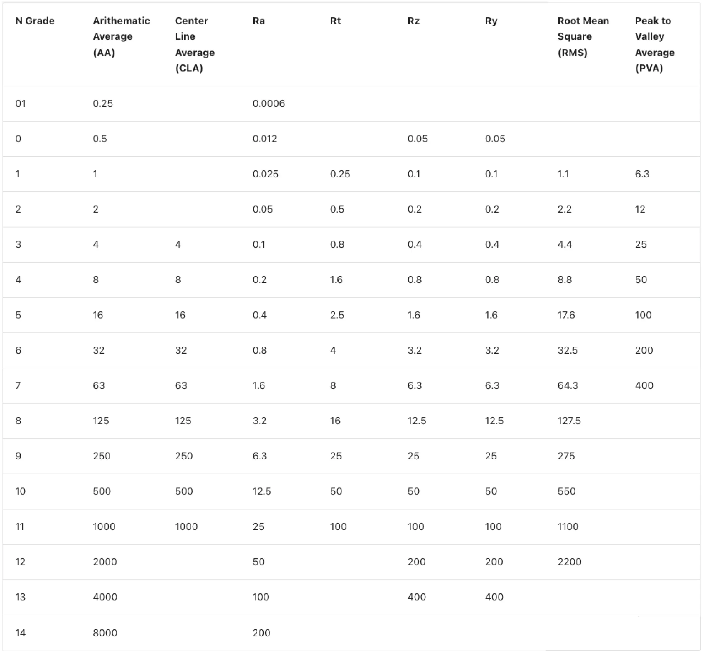
Tip: If you already work in N‑Grades, add the underlying parameter (e.g., Ra 1.6 µm (≈ N7)) to avoid ambiguity during inspection.
How Werk24 interprets and normalizes
- Understands symbols (basic / removal required / removal prohibited) and associates nearby text.
- Parses parameters (Ra, Rz, Rt, Rq), units (µm, µin), lay, sampling length, and stock allowance when present.
- Resolves scope: local callouts override general notes; “unless otherwise specified” applies to all unspecified faces.
- Normalizes output: consistent JSON (parameter, value, unit, lay, sampling length), plus N‑Grade where derivable.
- Flags ambiguity: mixed units, missing parameter name, or unsupported symbols get surfaced as warnings for review.
Common pitfalls (and how to avoid them)
- Bare numbers like “3.2” without Ra/Rz → always include the parameter and unit.
- Unnecessary tightness on non‑functional surfaces → use a sensible default note.
- Missing lay on seals/bearings → add ⊥, —, X, etc., to control friction and leakage.
- Mixing µm and µin in the same drawing → pick one; if you must mix, duplicate each value with its unit.
- No sampling length for Rz/Rt → include / 2.5 mm (or applicable), especially for coarse surfaces.