Creating Cloud-Ready Technical Drawings
TL;DR
This article discusses are your technical drawings cloud-ready, providing insights for engineering and manufacturing teams working with technical drawings.
Are your Technical Drawings cloud-ready?
No part without a Technical Drawing. To source a component based on drawings, they must be unambiguous and straightforward. But not all quality levels can be processed. For example, coffee stains on the drawings, drawings with substantial parts missing, pictures of the result on the drawing, overlapping sectionals, or the sectionals that touch the frame all make the drawing difficult for machines and humans to understand. They will cause friction in your sourcing process and thus introduce unnecessary costs.
Let’s review the best practices for creating engineering drawings using several samples.
Dont's For Technical Drawings
Some Technical Drawings make overly complicated project specifications. To prevent this, you should not do the following:
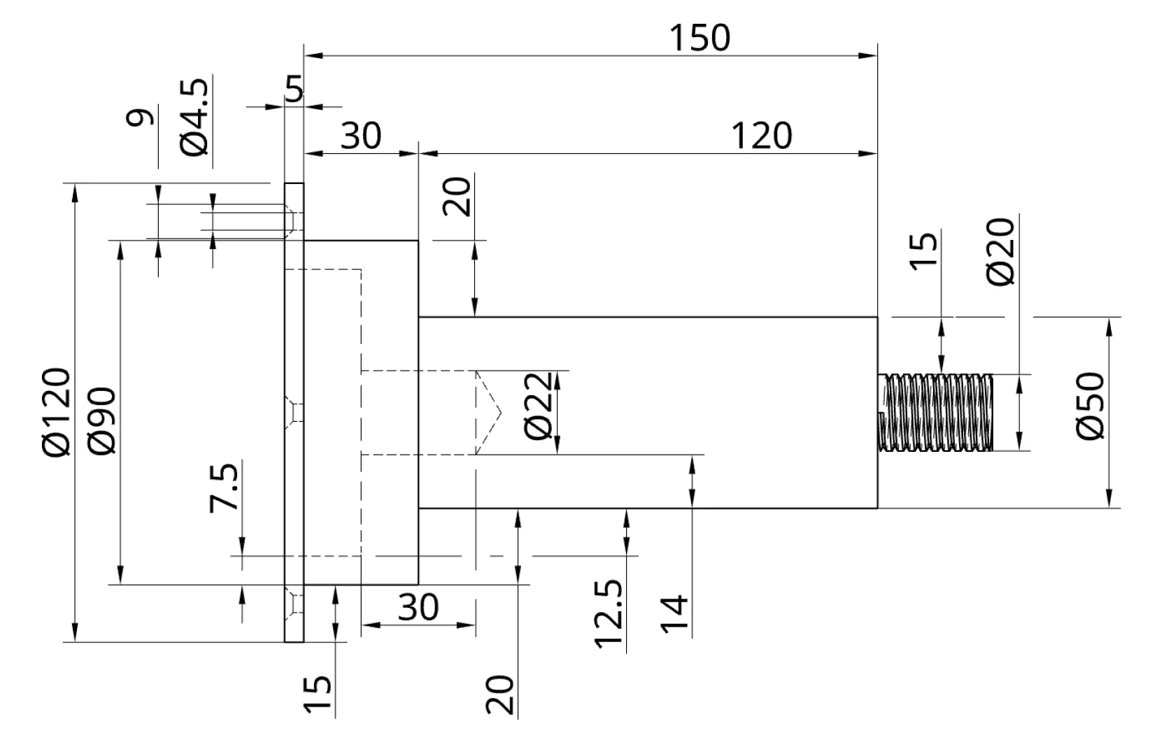
Avoid over-dimensioned engineering drawings
As designers, we recommend focusing your drawings on the most important parameters. To attain the parameters, initially, over-dimensioned drawings should be avoided because they generate confusion by drawing attention away from key aspects, as seen in the image. On the image, the dimensions are not friendly for manufacturers so they may not be able to identify what dimensions are important.
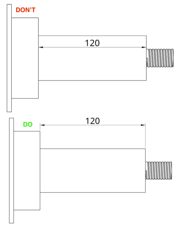
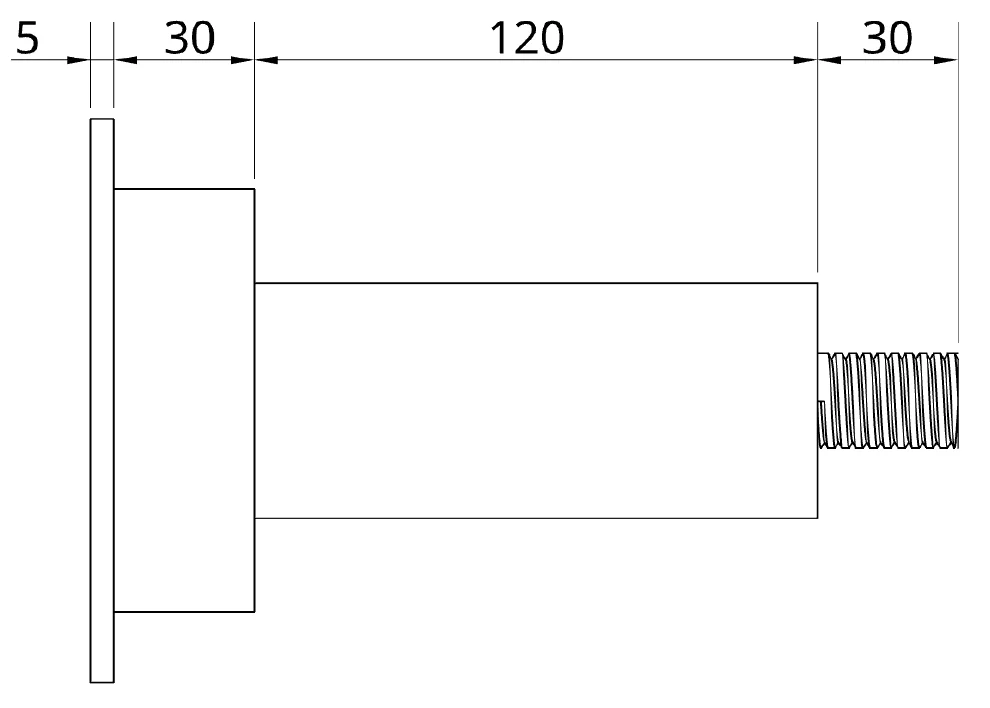
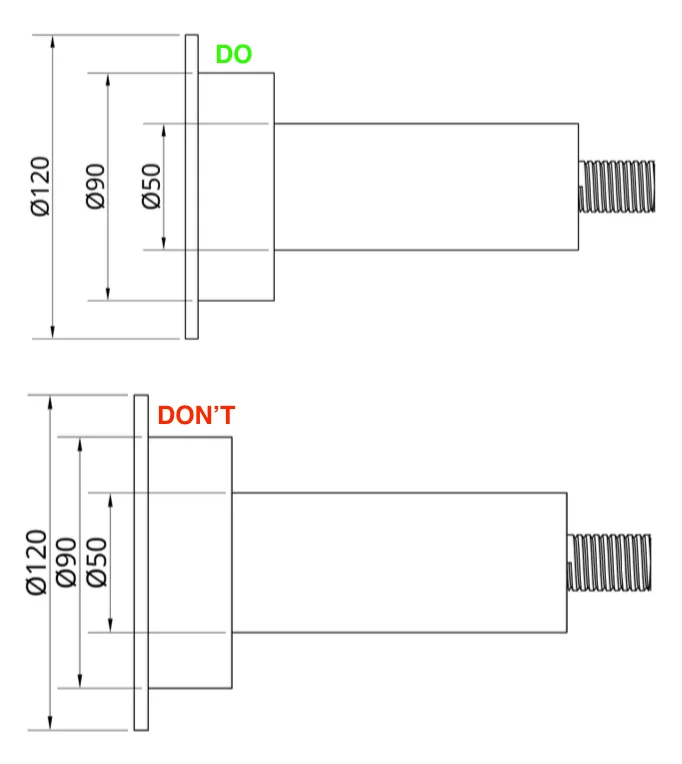
Long dimensions shouldn’t be closer than short dimensions
The alignment of dimensions is also significant for an organized structure. The short dimensions should be placed closest to the model, while the long ones should be positioned furthest away. One should always avoid crossing dimensions when possible. What shouldn't be is given in the image below.
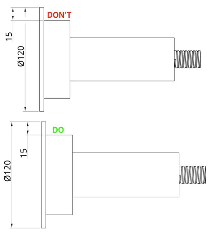
Dimensions shouldn’t be placed in the model area
It is essential to set the dimensions outside the part to ensure that the model remains clear.
Do’s For Technical Drawings
In addition to all these things that should not be done, there are crucial actions that should be taken to maintain a particular structure in technical drawings. Let's explore the important Do’s for the proper transfer of information from drawings.
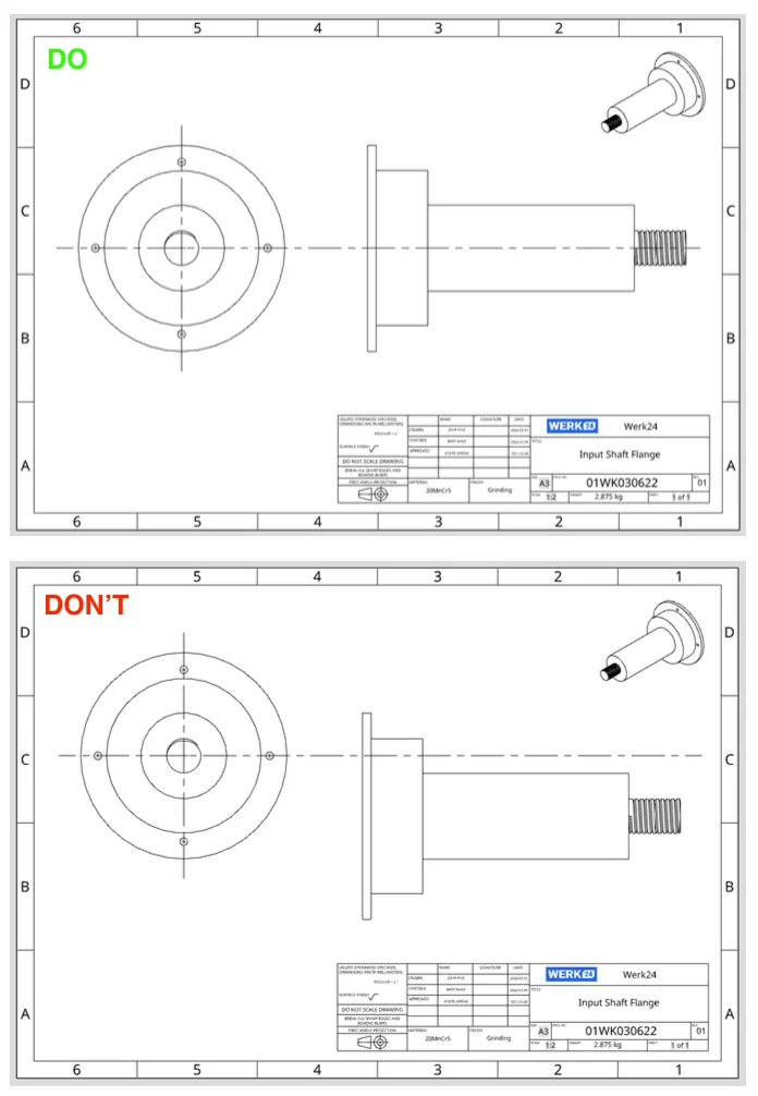
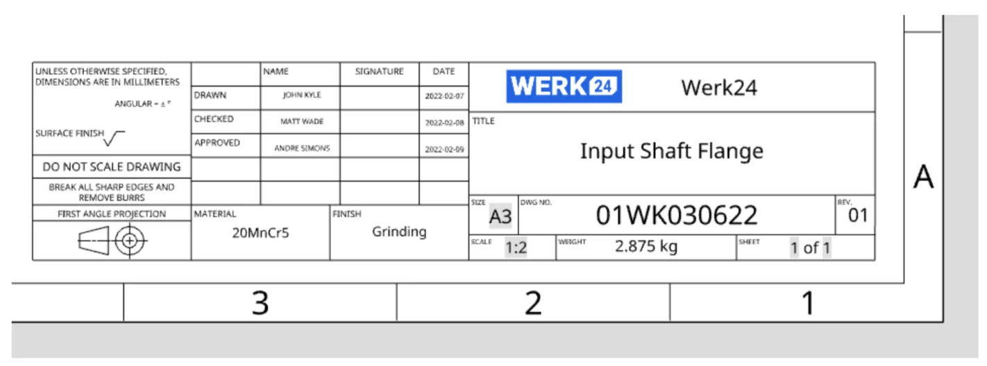
Title block should be placed right down in the corner
Title blocks have fixed places in the lower right corner of technical drawings as shown in the image.
Dimensions should line up in chain fashion
Bumpy-looking dimension lines, that are not perfectly aligned, makes it difficult to understand the dimensions. Therefore, dimensions should be put on technical drawings side by side as given on the image.
Dimensions should have space between them
Just as in all designs, white space is significant in technical drawings. For clarity, there should be sufficient spacing between parallel dimension lines.
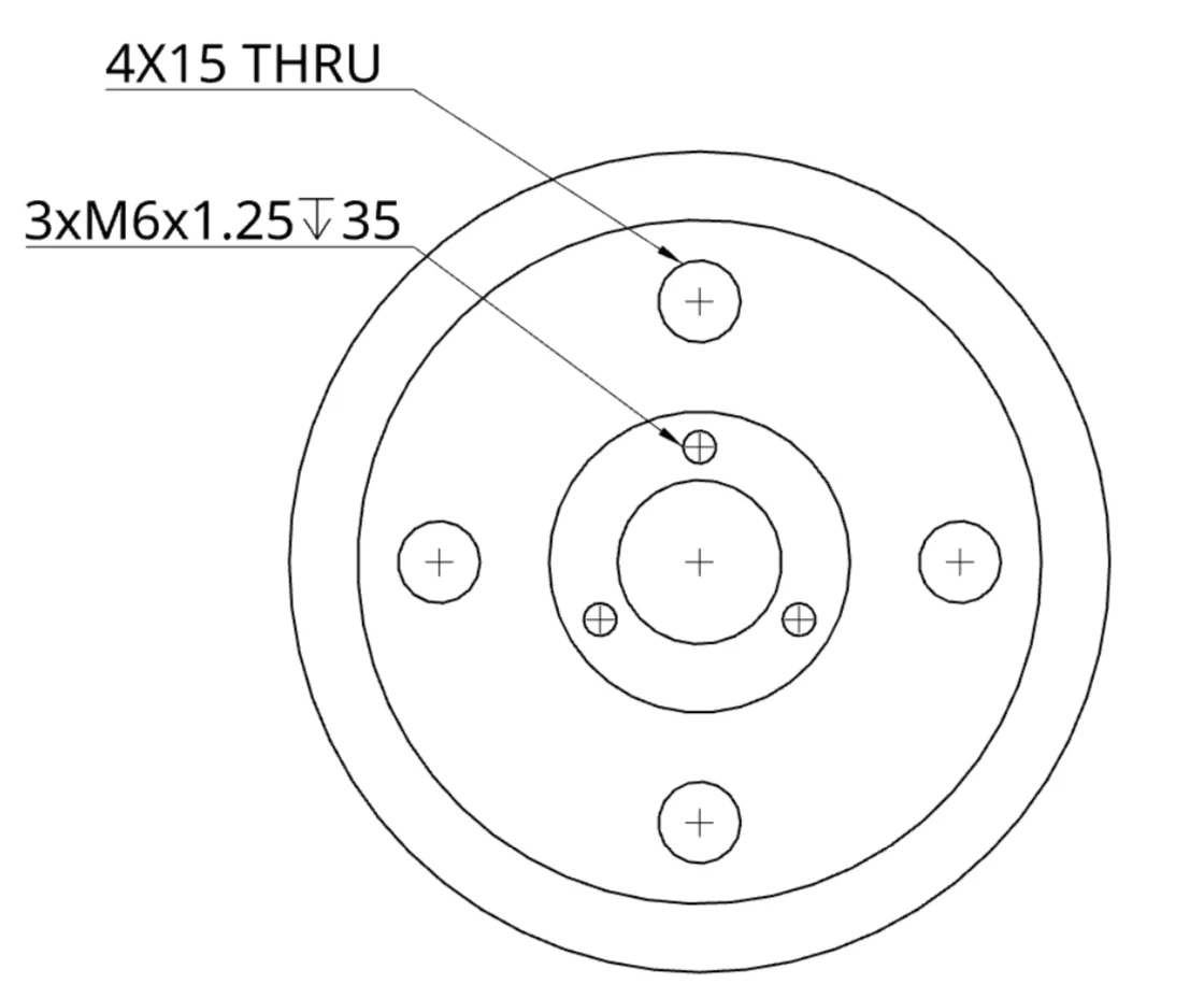
Multiple views of the same feature should be unified in a callout
A dimension labeled with "#X" indicates that the feature appears in the view a "Number" of times. "4X15 THRU" indicates that the visuals with the same function are used 4 times in the drawing by a single expression. Thus, unnecessary repetition of text in the drawing is prevented as in the image.
Views should be aligned
Part views in technical drawings shouldn’t be placed random on the paper. They must be aligned in order to have a clean appearance.