ISO vs ANSI Drawings
TL;DR
This article explores technical drawing standards and their applications, covering 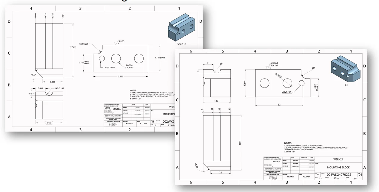 Do you know that technical drawing standards in for engineering and manufacturing professionals.
Do you know that technical drawing standards in Europe and United States completely differ from each other? Let us make a better understanding of the reasons behind these differences to learn the universal challenges that can be faced.
For both continents, technical drawings are representations of objects for technical purposes based on a set of conventions. In engineering and drawing standards, the objects can be depicted from several perspectives. There is more than one perspective in technical drawings because the countries in the EU and US have been using two different world standards in their engineering drawings. In Europe, they had adopted ISO standard, International Organizations of Standardization, whereas the US adopts a different method of depicting an object’s views on a manufacturing drawing, ANSI standard, American National Standards Institute.
The main differences in these two different world standards comprise of projection method, dimensions, general dimensions & tolerance standards, dimension syntax, units, drawing size, surface roughness standard, and material standard as shown in the table:
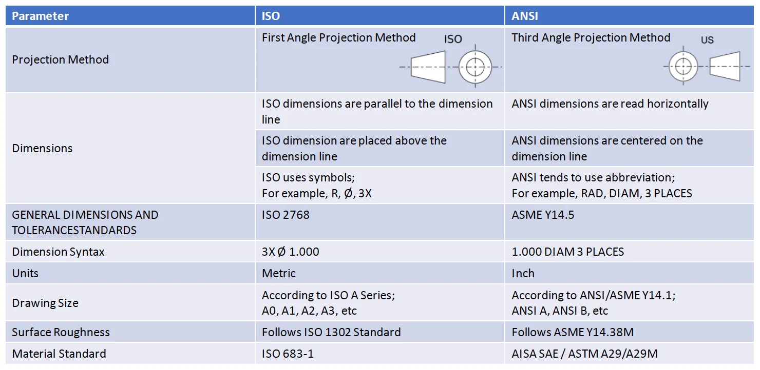
In Europe, they have been using the First Angle Projection Method and it became their standard where the object is placed between the observer and projection planes despite the US standard is Third Angle Projection method that the projection planes come between the object and observer as displayed on the table.
From the dimension's perspective, ISO dimensions are parallel to the dimensions line and placed above with them, conversely, ANSI dimensions are read horizontally and centered on the dimension line. In these dimensions, ANSI tends to use abbreviations such as RAD, DIAM, 3 PLACES despite the ISO using symbols including R, ∅, 3X. Moreover, the general dimension and tolerance standard of ISO is an international manufacturing standard, ISO 2768. On the part of ANSI, The American Society of Mechanical Engineers issued ASME Y14.5, a standard that suggested practices for declaring and interpreting Geometric Dimensions and Tolerances. The dimensions have different syntax in both standards as 3X ∅ 1.000 wherein ISO and 1.000 DIAM 3 PLACES in ANSI.
In consideration of units and sizes, ISO standard uses millimeters according to ISO A Series whereas ANSI standard uses inches under ASME Y14.1 in various drawing sizes given on the table.
Apart from the measurements, the engineering term of Surface Roughness which defines the smoothness of the referred surface is determined as ISO 1302 in EU standards meanwhile the parameter is specified as ASME Y14.38M in US standards.
Material standards are a blend of performance and prescriptive elements. The designation for material standards also differs between these continents. The most common material standards that are used in the EU and US are indicated in the table.
Engineers in the EU and US realized the need to standardize drawing techniques because the adoption of distinct standards makes both parties unilateral while they can gain from their techniques collaterally. A corporation that strives with technical drawings could not handle dealing with two separate standards and their various parameters. However, Werk24 is working on the readable version of both ISO and ANSI standards at the same time by innovative AI technology.