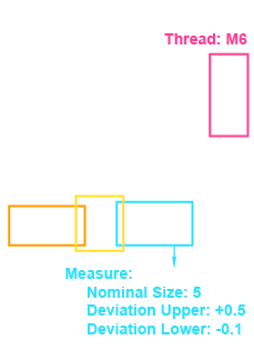
How Werk24 processes technical drawings
Werk24 transforms drawings into verified data and feasibility insights and writes it back into your systems. No templates, no parsers, results in your format.
1) Your system sends a manufacturing drawing
ERP or PLM send a technical drawing (PDF, TIFF, JPEG, JP2, PNG, BMP) to the API. Multi -page scans and archive copies are in scope.
Ops Teams
- Master supplier variety and decades of archives without preparatory work.
Developer Experience
- Integration via HTTPS-Post or Python-SDK
2) Werk24 understands the engineering jargon
We interpret meta data and PMI in context - dimensions, tolerances (GD&T), threads, surfaces - and deliver confidences per field.
Ops Teams
- Over 95 % accuracy as with experienced manufacturing engineers.
Developer Experience
- Deterministic, typed JSON, which can be easily validated and mapped to ERP/PLM data structures.
3) Immediate feasibility analysis & manufacturing indicators
Overall dimensions (raw/finished), process information (DIN 8580), volumes and feasibility flags keep offers realistically.
Ops Teams
- Go/no-go decisions directly at reception of the RfQ, fewer surprises.
Developer Experience
- Optional webhooks or callbacks for dark processing and analyzes.
4) Structured data back into ERP and PLM systems
By default JSON-or Individual data formats (CSV, XML, ERP/PLM scheme). Results are handed over to your down-stream systems via webhook or callback.
Ops Teams
- Rollout without process change, low acceptance hurdles.
Developer Experience
- File data exactly where you need it - via webhook or callback.
Data extraction from manufacturing drawings
Werk24 is more than OCR - we understand technical semantics . Each output is normalized , pixel precise traceable (x/y/bbox) and ready for ERP/PLM/CAD-CAM .
- No training data required
- Confidence & Evidence trace per field
- GD&T-understanding (ISO/Asme)
- API, Webhooks & Python-Client
Drawing-automation
Upload the drawing and receive structured JSON — no model training required. Integrates with costing, ERP/PLM, CAD/CAM or analytics via Rest-API, webhooks and Python client . We calibrate on your data for individual rules or Quality Gates .
Supported drawing formats
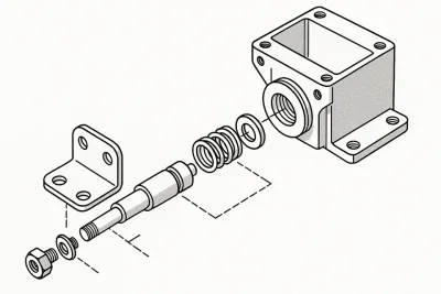
Werk24 focuses on mechanical drawings - this enables maximum accuracy, even with scans and old stocks.
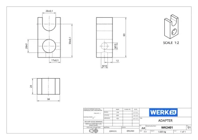
Supported drawings Supported example
- Component drawings (parts, details)
- Assembly drawings (mechanics & substructure groups)
- Sufficient quality scans (≥ 200dpi, recommended 300dpi)
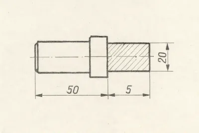
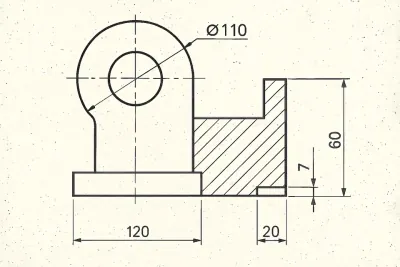
- Clean, hand -drawn technical drawings (complete dimensions & notes)
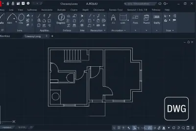
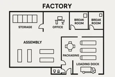
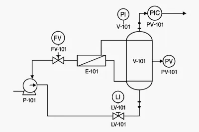
Non -supported drawings and files Unsupported example
- Building and architecture floor plans
- P&ID assembly schemes or process flow diagrams
- Electrical or wiring plans
- CAD native files (DWG, DXF)-please export as a PDF or raster
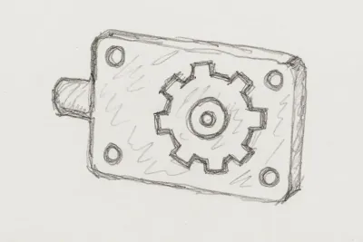
- Sketches, whiteboards or incomplete drawings
Examples


Werk24's output format matches your system's
Choose between Standard API for quick entry or Custom Profile that matches your ERP/PLM/MES/QMS requirements-including field names, types, units and formats.
Mode A – Standard-API-Integration
- Stable, versioned scheme
- Fast onboarding, full documentation, and SDKs
- Ideal for pilot projects, calculation, analytics
Mode B - Custom Manufacturing Profile
- Custom keys, enums and unit policies
- CSV, JSON or XML;Push or pull
- Ideal for regulated or legacy environments
Which output format suits your tech stack?
Select the Standard API if …
- You want the fastest integration path
- Werk24 keys can take over directly
- Appreciate the backward compatible versions from a single source
Choose the Custom Profile, if …
- Your systems request fixed field names/types
- CSV/XML is required due to quality or regulatory standards
- You require strict units, enums, or rounding rules
Why the mapping stays consistent
- Semantic core: We normalize Asme/ISO styles and languages before formatting them to your schema.
- understandable: Each field refers to evidence for audits and ppap/fai.
- typed & validated: units, areas and enums are checked before delivery.
Ready for your individual scheme?
Send us a field list, a sample export or a JSON scheme-we deliver an immediately usable output format.
Why Werk24 surpasses OCR and generic AI in drawings
Werk24 is built for technical drawings: deterministic, auditable and ready for ERP, PLM and MES integration.
| Capability | Generic OCR | Generic LLM | Werk24 |
|---|---|---|---|
| Understands GD&T (Asme Y14.5), ISO tolerances, threads/fits, surfaces | Sometimes unreliable | Matching an engineer's accuracy † | |
| Deterministic, structured edition | Only raw text | Free-form language | Clean Json or your scheme |
| Processes scans/old stocks (low DPI, fax artifacts) | High error rate | Missing context | Built for 20-30 years old archives |
| Confidence & Quality Gates per field | Automatic handling of outliers | ||
| Traceability & evidence (BBox-anchor, snapshots) | Non -reproducible | Reviewable evidence | |
| Integration in ERP/PLM/MES | Manual Copy & Paste | Additional connection necessary | Webhooks & Individual Mappings |
| Compliance & auditability | Unavailable | Non -guaranteed | SLAs, EU/USA data standards |
| Works without training data | Template-bound | Needs annotations | Out-of-the-box |
| Standard & language independence | Depending on the prompt | Asme↔ISOo;From/en/es/nl/ja/it | |
| Zero-Retention-Option | Non -offered | Non -guaranteed | In enterprise packages |
† typical of supported annotations;Results vary depending on the scanning quality and signing standard.
Proven results in the automated processing of drawing
With Werk24, teams in Europe and North America are successfully accelerating RFQs, reducing rework and standardizing drawing acceptance.
Faster RFQ processing for technical drawings
Observed in supported annotations with a standardized intake.
High PMI accuracy in standard annotations
With individual quality gate up to 99 %.
Typical processing time per page
Provisioned & Enterprise tiers offer parallel jobs.
Flexible data locations
Encrypted in the event of transmission and storage; Zero retention optional.

"The PMI extraction of Werk24 increases our calculation accuracy."
— Christoph B. Roessner & Adrian Raidt, Founders of Laserhub
"With Werk24, thousands of drawings can be processed in a few hours."
-Henk Jonker, Co-Founder, DimanexFrom developer: inside for developers: inside
Clean APIs, predictable JSON, confidences and webhooks. From PDF to production in hours instead of weeks.
Price overview
Simple structure: monthly basic fee + per-drawing-page fee.
Service Tier
from € 990 / month
- 1–3 parallele jobs
- Standard API output
- Support via E-Mail & Slack
- Data residency: EU or USA
Enterprise
Individually
- Dedicated environment
- Custom Output Mapping
- SLA & compliance extensions
Talk to us for Govcloud, ITAR compliance or special compliance requirements.
ROI-Calculator
Estimate your monthly savings with Werk24
Monthly savings
292 Std. Saved per month
Werk24 costs
Basic fee + side price
Net ROI
Per month
Break-even
Time saving per drawing for cost recovery
FAQ for the Auomated Processing of Technical Drawings
The most common questions of engineering and operations teams- clearly answered.
Which drawing formats are supported?
CAD native formats (DWG, DXF) are not supported , since these require licenses for the respective software. We reach the highest accuracy with the focus on 2D drawings. Zur Formatübersicht →
How accurate is Werk24?
How do I get the results?
Are there SDKs and APIs?
- Python-SDK on PyPI to get started immediately
- HTTPS-REST-API with Webhooks for every language
- Structured endpoints for meta data, features, insights, redactions, balloons und thumbnails
Where are my data processed?
How fast is the processing?
What is the price model?
Can I test Werk24?
Is Werk24 available worldwide?
Do I need training data?
Is Werk24 saving my drawings?
Did not find an answer to your question? Our team is happy to help personally.
Talk to an expert